 1/4" plywood panels cut to fit the frame. Joined with drywall
screws...after drilling a pilot hole and countersinking each hole so that the
final layout is flush with the panel.
1/4" plywood panels cut to fit the frame. Joined with drywall
screws...after drilling a pilot hole and countersinking each hole so that the
final layout is flush with the panel. Construction
Update
Week 3
Beginning to look a little more like 'something'!
I began building the pedestal cover panels. The Captains side will be fixed in place ...you cannot remove the panels on this side and they will be sealed and painted over. The F/O side will be removable since we will have a fair number of components housed in this area (FMC computer, MDC access, Throttles and Power Quadrant).
I was also able to begin on the Main Instrument Panel (fondly known as 'MIP'...or 'DIP' when it gets tough!). The key here is to get the right ANGLE. Took many measurements to try to get it accurate...finally just decided to go with what looks best.
Drawings: (n/a)
Dimensions: (n/a)
Photos:
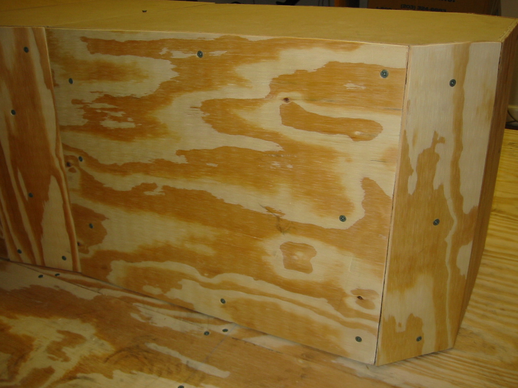
1/4" plywood panels cut to fit the frame. Joined with drywall
screws...after drilling a pilot hole and countersinking each hole so that the
final layout is flush with the panel.
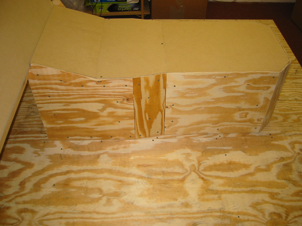
 The back of the pedestal is very difficult...I basically created all the other
panels to fit to the frame, then this rear panel is the final 'catch-all' to
make up for my measurement differences. Requires angles and repeated
measurement.
The back of the pedestal is very difficult...I basically created all the other
panels to fit to the frame, then this rear panel is the final 'catch-all' to
make up for my measurement differences. Requires angles and repeated
measurement.
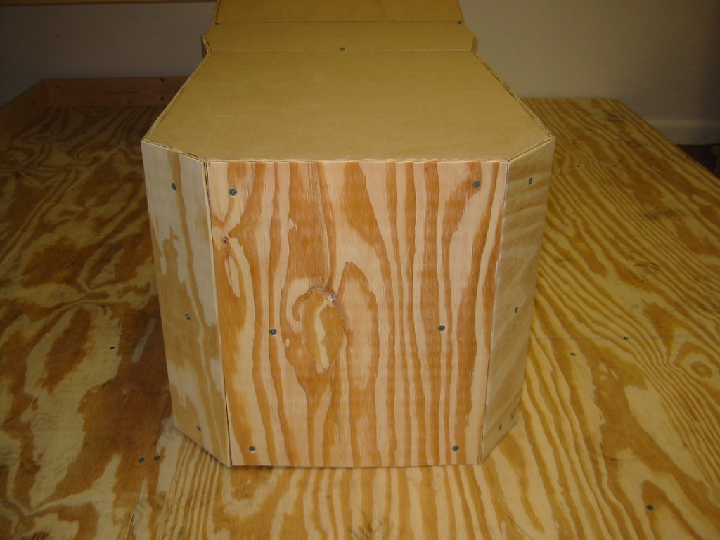
 Captain side done. Gaps will be filled with wood putty and sanded to match the
rest of the frame.
Captain side done. Gaps will be filled with wood putty and sanded to match the
rest of the frame.
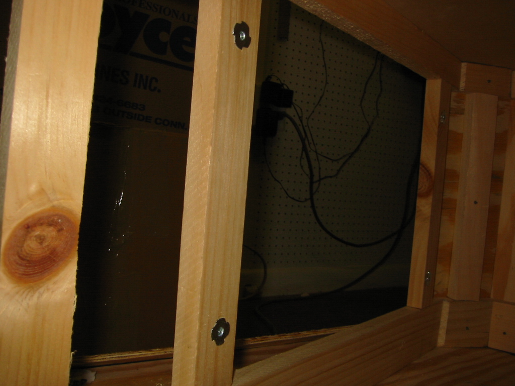 F/O side panels are removable. I found these fasteners at Home Depot. They allow
me to attach and remove panels as often as I like, using machine screws. You
cannot do this with regular wood screws.
F/O side panels are removable. I found these fasteners at Home Depot. They allow
me to attach and remove panels as often as I like, using machine screws. You
cannot do this with regular wood screws.
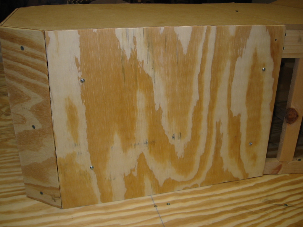 Removable panel attached. Note the 4 round head machine screws holding it in
place.
Removable panel attached. Note the 4 round head machine screws holding it in
place.
 Cross member put in place to provide structural support as I work on the rest of
the cockpit.
Cross member put in place to provide structural support as I work on the rest of
the cockpit.
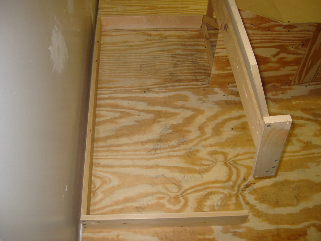 Framing in place to support the Main Instrument Panel (MIP) work
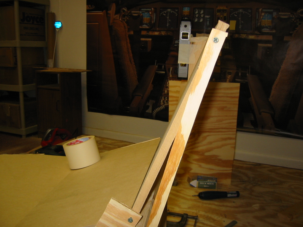 Attempting to create a 30 degree angle on the MIP using level and a pre-cut
wedge.
Attempting to create a 30 degree angle on the MIP using level and a pre-cut
wedge.
 My genius at work! I have no protractor or angle tool. So, using
trigonometry, I cut a wood wedge with the correct angles and used the level to
get to the end result. Probably easier ways to do this...but let me bask
in the fact that I FINALLY used trigonometry for something useful in life!!
My genius at work! I have no protractor or angle tool. So, using
trigonometry, I cut a wood wedge with the correct angles and used the level to
get to the end result. Probably easier ways to do this...but let me bask
in the fact that I FINALLY used trigonometry for something useful in life!!
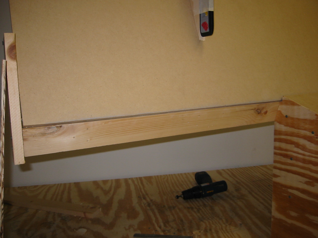 The lower support arm in place.
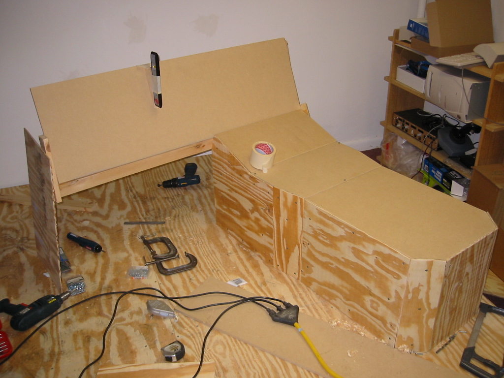 Starting to look recognizable as a cockpit. Without the F/O side, it is a
little odd...but we'll get to that in due time.
Starting to look recognizable as a cockpit. Without the F/O side, it is a
little odd...but we'll get to that in due time.
 Captains side of the pedestal. Lot's of screws...but they will be filled and
sanded over in the final stages.
Captains side of the pedestal. Lot's of screws...but they will be filled and
sanded over in the final stages.
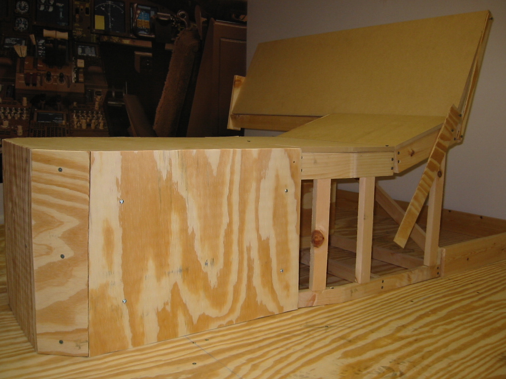 Here we are for this weekend. I left a few pieces of wood in place to hold
the MIP in place as I build the rest of the cockpit. Not a bad job!
Here we are for this weekend. I left a few pieces of wood in place to hold
the MIP in place as I build the rest of the cockpit. Not a bad job!
Reflections. (this is where I sit on my work stool and stare at my creation for a few long minutes and visualize flying through the air in the finished product...I usually am covered in sweat, sawdust, blood and pizza crust...but I am in 'the zone'! I also admit my failings to myself, and try to learn for the next phase of the project...or just blow it off and keep moving!)
- I originally intended to make only the Captain's side of the simulator. I think I will be overcome with the desire to be 'real' and will end up making the full thing.
- Clean up after you are done. Especially when working on carpeted areas. If you leave dust and items on the carpet, they gradually get pressed into the fiber of the carpet and NO amount of brushing or vacuuming will take it out! The impact of a clean workspace cannot be understated...
See you next week!